DSL Theory
A DSL is basically a custom scripting or “little language” which is designed to make the construction of particular types of application easier. From this perspective old favourites such as SQL and PHP are DSLs. Using the DSL approach is essentially the old “bottom up” technique where you first of all write a basic subroutine library of things that might be helpful in tackling a class of problems. For example, if you need to solve differential equations then a library of differential equation solver subroutines is a good idea.The trouble with “bottom up” is that it is often unfocused and can waste resources as you attempt to create useful utilities in a vacuum. There are people who advocate DSL as part of a new and more advanced approach to application architecture, which aims to put DSLs into the hands of non-programming “domain specialists”. An associated idea that is often proposed along with DSLs is that of “software factories”. Put simply, a software factory is an old-fashioned code generator invested with some new jargon and some new philosophy. A software factory can make use of or generate a DSL.
DSL Tools
Microsoft is currently very keen on the idea of both DSLs and software factories. DSL Tools V1 is available for download.Once downloaded all you have to do is install it on a machine that has any one of the following already installed: Visual Studio 2005 Professional Edition, Team Edition for Software Architects, Team Edition for Software Developers, Team Edition for Software Testers or Team Suite. I used the Professional Edition for all of the examples in this article.
Once you have DSL Tools installed you will find that you have additional project types, new help files and some extra samples. The new project types are found in Other Project Types, Extensibility and the one that is of interest at the moment is Domain-Specific Language Designer. The bad news is that the documentation, examples, white papers and even the video introductions are truly awful. They all spend far too much time on the “fluff” and mostly ignore the most obvious questions that a programmer new to the DSL tools is likely to have. Most of the examples are too complex and appear to involve “magic” – instructions such as “now paste the following XML into a new file” without any explanation of where the XML came from or what it does is hocus-pocus as far as the beginner is concerned. Rather than spending a few thousand words on explaining how you can change the colour of a diagram shape, this article concentrates on the missing element in the documentation – how to use DSL Tools to actually generate some code from a custom diagram. Once you know how to do this then the documentation starts to make a little more sense.
Overview
DSL Tools takes a graphical approach to DSL construction. When you start a new DSL project what you are provided with is a DSL Designer that allows you to create a “diagram editor” in the form of a generated VS Designer. This might seem confusing because what you have is a Designer Designer which you use to create a custom Designer which the end user then uses to create a diagram and generate code. It begins to make more sense when you start to make use of it, but it helps to realise that you first use the DSL Designer to specify the type of diagram the user can create – a flow chart, class diagram, workflow diagram – essentially any collection of boxes and arrows subject to the rules that you specify for how they can be arranged to create a diagram.Once you have used the DSL Designer to specify your custom designer you use the standard templates to generate code which you then run. The generated code creates your custom designer which you can run in VS. It has a toolbox full of the entities you specified and you can use it to create an instance of the type of diagram you specified.
This much is explained at great length in the documentation. The next step, however, is to add to the custom designer code templates that generate code from the instance of custom diagram we have created, and this isn’t really explained. For example, suppose we want to create a custom VS Designer that allows the user to place “Hello” blocks on a diagram and link them up in a particular order. The code then generated from the custom Designer could display web pages that state “Hello World”, one for each Hello block in the order in which they are connected and with other properties taken from each block – colour, language, greeting type.
To create the custom Designer we first use the DSL Designer to specify the shapes and rules for the custom Designer, generate the code and run the result. We now have a Custom Hello World designer but no code generators. This means the user can construct diagrams but nothing happens if they try to generate code. The final step is to write at least one code template that uses information in the diagram instance to generate suitable code.
Hello World diagram
As you might have suspected, the example described above is going to be the basis of our hand-on first DSL project. Yes, we are going to create a “Hello World Designer”, complete with code generation. The objective will be to keep things as simple as possible so we will start with a default custom diagram, accepting all defaults, and write a code generator for HTML pages ignoring any links that the user has set up on the diagram. That is, if the user places three “Hello” blocks on the diagram, the generated web page has three “Hello” messages – very simple, but it serves to demonstrate the basic way the generated code depends on the diagram.Time to get started implementing the project. Open Visual Studio 2005, select New Project and then navigate to Other Project Types, Extensiblity and select Domain-Specific Language Designer. Assign the new project the name HelloModel and a suitable storage location.
When the DSL Wizard moves on the next step is to select a suitable template for the custom Designer. In our case the very basic MinimalLanguage template will do, and we can also accept the default name HelloModel for the DSL generated. In the next step of the Wizard we can specify an extension to be associated with the custom editor – enter .HELLO in this case – and leave everything else as the default. The next page allows you to set details of the names and namespace used by the model. In this case enter VSJ for the company and accept all the defaults. The final page of the Wizard generates a strong name key file and completes the specification of the project. If you click finish the project will be generated.
After a few seconds of waiting you should see a DSLDefinition.dsl file displayed as a Designer diagram. By default when you first load the project code is automatically generated from the diagram. If you make any changes you might well need to re-generate the code before running the project. If you examine the diagram your first thoughts might be that this looks complicated. Reading the diagram shown in Figure 1 reveals most of what is going on.
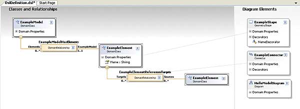
Figure 1: The default diagram
You can see that the diagram is made up of a number of “blocks” or DomainClasses linked by a number of DomainRelationships. The first block is called “ExampleModel” – you can think of this as the topmost block that contains all of the other blocks that the user might put on the diagram. These other blocks are related to the ExampleModel block by the ExampleModelHasElements relationship. If you look closely at Elements end of this relationship you will see the notation 0..*, which means that there can be 0 or many Elements connected to the ExampleModel. At the other end of the relationship you will see the notation 1..1, meaning that there is just 1 ExampleModel block, i.e. this relationship is one-many which is what you would expect.
Moving on you can also see that there is an ExampleElement block with a single property “Name”. This just means that the user can place this block on the diagram and assign each one a name. You can add other user-settable properties to blocks, but for the moment a Name property is sufficient. Each ExampleElement can be related to other example elements by an ExampleElementReferencesTargets DomainRelationship. You can also see that in this case both Targets and Sources are set to be “many”, and this allows the user to place multiple ExampleElement blocks on the diagram and link them using this relationship in a many-to-many way. If you are finding this hard to follow it becomes a lot easier once you have seen the generated custom Designer. Exactly how the custom Designer’s code is generated will also become clear once we have added some generated code of our own.
Testing the custom Designer
Now we can move to the next stage of creating a custom Designer. Make sure that all of the generated code is up-to-date – in the Solution Explorer click the new Transform All Templates button. Next start the project running using Debug, Start Debugging or press F5. What happens next might be slightly unexpected. A new copy of Visual Studio opens with your custom Designer already loaded plus a sample and a test diagram. To see how things work, open the Test.hello file using the Solution Explorer. You will see a blank diagram, and if you open the Toolbox you will see that it contains ExampleElement and ExampleRelationship. You can now drag ExampleElements onto the diagram and connect them up using the ExampleRelationship. You will discover that you can use the ExampleRelationship to create many-to-many connections. After playing with the diagram for a while you should become happy about how the DSL Designer determines the way the custom Designer behaves – and you should become bored very quickly! There isn’t much that this Designer can do for you – and in particular there is no generated code based on the diagram you draw (see Figure 2).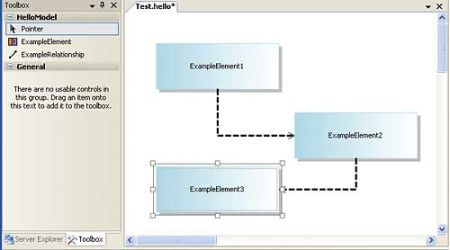
Figure 2: A sample diagram drawn with the custom designer
Generating some code
The key to code generation in all DSL models is the use of TextTempate or .tt files. These can contain a mixture of code which is executed to generate more code, and code which can be simply quoted into the generated code. This “dual use” makes the TextTemplate difficult to fathom at first, but if you have had any encounters with meta-languages, or indeed with the way that HTML is generated using PHP or the DOM, then you should be in a better position to follow what is going on.Another puzzle to solve is exactly where the TextTemplates should be included in the project – in the original DSL Designer or in the custom Designer that it generated? Clearly the answer is that if you want to modify or augment the code generated by the DSL Designer, add to the large number of TextTemplates it already has. If you want to add code generation to the custom Designer then the TextTemplate needs to be included in the generated project. It seems obvious when put so clearly, but it is a little odd to be adding files to a generated project. The good news is that any files you do add are preserved if you re-generate the custom Designer.
To add a TextTemplate to the project simply use the Add,New Item in the Solution Explorer and create a Text File called Hello.tt. You don’t have to use the .tt extension, but if you do, two things happen automatically. The first is that the files “Custom Tool” is set to TextTemplatingFileGenerator, and second this custom tool is run on the file to generate some code. If you use any other extension for the TextTemplate then you have to manually set the CustomTool property to the template processor – usually TextTemplatingFileGenerator.
In this case of course the TextTemplate is blank and hence so is the generated code file. If you look in the Solution Explorer you should see Hello.cs just below Hello.tt in the hierarchy. By default generated code files are .cs files and are supposed to contain C# code – but you can change this (see Figure 3).
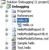
Figure 3: The generated code file
Anything that you put into the TextTemplate file is simply transferred to the generated code unmodified unless is it enclosed by “<#” and “#>” brackets, when it is interpreted as an instruction of some sort. Instructions are obeyed and they either modify the way the code is generated or they result in dynamic code generation. The simplest code generator we can implement produces a single HTML page with no dynamic code, i.e. no code that depends on the diagram the user has created. The first thing we have to do is change the extension of the generated code file:
<#@ output extension=”.htm” #>This is an example of one of the five built-in directives that change the way the code is generated. In this case the output directive can change the extension, and optionally the encoding, used for the output file.
The remainder of the TextTemplate take the form of HTML that is simply quoted directly into the generated code:
<html
xmlns=”http://www.w3.org/1999/xhtml” >
	<head>
		<title>Hello World</title>
	</head>
	<body>
		<h1>Hello World</h1>
	</body>
</html>
If you enter the directive and the quoted HTML into the Hello.tt file, right-click and select Run Custom Tool, you will see that the Hello.cs file has turned into a Hello.htm file and if you right-click on this and select View in Browser you will see the Hello World Web page.
Bring in the model
If this is as far as code generation goes it isn’t very impressive, and certainly doesn’t need the custom Designer! To do anything meaningful we really need to involve the diagram of the model that the user has created and use dynamic code generation. A TextTemplate can contain a number of different types of dynamic code generation. As already mentioned if you have text enclosed by <# and #> then the text is interpreted as code (C# by default) to be executed during code generation. For example, if you include:<# WriteLine(“Hello”); #>…then the generated code contains the text Hello. An expression is an even more direct way of generating dynamic code. If you use
<#= ExpressionCode #>…then the ExpressionCode is evaluated and the result inserted into the generated code. For example:
<#= 2*2+1; #>…inserts the digit 5 into the generated code.
This is all very well and you can probably now see how to generate code dynamically from the template, but how do you access details of the diagram the user has created?
The answer is that when the user creates a diagram the system creates a “directive processor” which contains classes and methods that give access to the model as created by the user. Before you can use these classes and methods you have to call the generated directive processor to add them to your template. The only problem with this task is the complexity of the names involved. The directive processor is by default called DirectiveProcessor.cs and stored in the GeneratedCode directory of the project, HelloModel\Dsl\GeneratedCode in the case of our example. The directive processor is used as a custom directive:
<#@ DSLname processor=
	“DSLnameDirectiveProcessor”
	requires=”fileName=’diagram.ext’” #>
The DSLname is replaced by the name of your custom DSL – HelloModel in this case. The “requires” clause specifies the instance of the custom diagram that you want to process e.g. Test.hello. You can also specify a “provides” clause to specify what the resulting generated class model should be called. By default it’s given the same name as the DSL, i.e. DSLname. To make use of the generated class we also need to specify a base class that it will be derived from and this requires a “template” directive.
So to add access the model in the generated code we need to first add two lines to the start of the Hello.tt file:
<#@ template inherits=
	”Microsoft.VisualStudio.
	TextTemplating.VSHost.
	ModelingTextTransformation”#>
<#@ HelloModel processor=
	“HelloModelDirectiveProcessor”
	requires=”fileName=’Test.hello’” #>
Now the code within the template can access the model corresponding to the diagram that the user has drawn in Test.hello.
Now we can write a simple loop that retrieves the name of each box placed on the diagram by the user and uses it to create a “Hello World” message from each box:
<html xmlns=
	”http://www.w3.org/1999/xhtml” >
	<head>
		<title>Hello World</title>
	</head>
	<body>
	<#
		foreach(ExampleElement box in
			this.ExampleModel.Elements)
		{
	#>
	<p>Hello World from
		<#=box.Name#></p>
	<#
		}
	#>
	</body>
</html>
Notice that we have a mixture of static and dynamic code generation. The first part of the template always produces the same HTML. The dynamic generation starts at the foreach loop. Notice that the “this” is necessary to make it work with the diagram instance, and that the ExampleModel is the topmost domain class as specified in the DSL designer. The ExampleModel has an Elements collection, which contains all of the ExampleElement domain classes corresponding to each block the user has placed on the diagram. We simply step through each one and use an expression to insert the block’s name into the HTML code generated. If you select the TextTemplate, right click and select Run Custom Tool then a new HTML file will be generated, and if the user has placed three blocks on the diagram it will contain:
<html xmlns=
	”http://www.w3.org/1999/xhtml” >
	<head>
		<title>Hello World</title>
	</head>
	<body>
		<p>Hello World from
			ExampleElement1</p>
		<p>Hello World from
			ExampleElement2</p>
		<p>Hello World from
			ExampleElement3</p>
	</body>
</html>
Deeper into the model
The next step is to look into ways of using the generated model in more sophisticated ways. For example, we could write code that generates greetings in the order that the blocks are joined together. This raises a few practical problems because in this case the relationships can be many-to-many, and it is possible to draw a diagram with no unique single route through from block to block. Such problems can be overcome either by making the code clever or by going back to the DSL Designer and putting restrictions on the type of diagram the user can generate, e.g. by making the links one-to-one, say.There is also the more prosaic reason that moving on to work with more sophisticated aspects of the model is more difficult than you might think. There is virtually no documentation of the class structure, only very specific examples that really don’t help. The only solution I’ve found to the documentation problem is to read the generated code files in the DSL Designer. For example, if you open the file DomainClasses.cs in the original project you will find the definition for the classes ExampleModel and ExampleElement. Looking closely at ExampleElement reveals that it has a Targets property which returns a LinkedElementCollection. If you lookup the definition of LinkedElementCollection you will further discover that this is a collection of ExampleElement objects. With this information we can now generate code that lists all of the elements that each element is linked to.
The changes needed to the generated code are:
<body>
	<#
		foreach(ExampleElement box in
			this.ExampleModel.Elements)
		{
	#>
	<p>Hello World from
		<#=box.Name#></p>
	<#
		foreach(ExampleElement targ in
			box.Targets)
			{
	#>
	<p> is connected to
		<#=targ.Name#></p>
	<#
			};
		}
	#>
</body>
Notice that the outer foreach loop still steps through each of the blocks placed on the diagram, but the second foreach loop uses each block’s Targets property to list all of the blocks it is connected to.
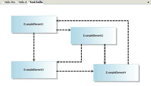
Figure 4: A complicated connected diagram
For example, if the user draws the diagram shown in Figure 4 then the resulting generated HTML is:
<html xmlns=
	”http://www.w3.org/1999/xhtml” >
	<head>
		<title>Hello World</title>
	</head>
	<body>
		<p>Hello World from
			ExampleElement1</p>
		<p> is connected to
			ExampleElement3 </p>
		<p> is connected to
			ExampleElement2 </p>
		<p>Hello World from
			ExampleElement2</p>
		<p> is connected to
			ExampleElement3 </p>
		<p> is connected to
			ExampleElement4 </p>
		<p>Hello World from
			ExampleElement3</p>
		<p> is connected to
			ExampleElement4 </p>
		<p>Hello World from
			ExampleElement4</p>
		<p> is connected to
			ExampleElement1 </p>
	</body>
</html>
Similarly, by reading the other generated code files you should be able to work out how to generate code based on just about any aspect of the diagram. Notice that it’s very easy to add custom properties to the model elements and to use this to change the generated code. For example, adding a “country” property to the ExampleElement allows the code generator to test it and generate a “Hello World” in the appropriate language.
Where next?
After following this description and the simple examples you should have a fairly clear idea of the overall structure of the DSL Tools. What you need to find out to make more progress is how to use the DSL Designer to specify the exact type of diagram you want to allow the users to construct. You can construct class diagrams using templates for Task Flow, Class Diagrams, Component Diagrams and the Minimal Language type that we used in the example. Notice that these are just starting points and you can customise the diagram as much as you like and mostly this is all relatively easy.If you are going to generate either C# or VB code then you are also going to have to implement a way of using it. The generated code in the Designer is part of a class library and there is no Main function or form to get an application started if you select Run. In other words, you have to either use another project which uses your generated class library, or generate a main function for a console application, say. Avoiding these difficulties is the main reason the examples used HTML rather than C#. Notice also that you can generate warning messages, documentation and reports using the same code generation approach.
Step forward or back?
After using DSL Tools for a while I’m not 100% convinced that this is useful. For a code generation tool to catch on it has to be significantly easier than the task it replaces. At the moment DSL Tools are difficult to use and the initial learning curve is very steep so you don’t seem to get very much back for the investment. The visual designers are fairly easy to use, even if they are overflowing with new jargon and a high degree of what appears to be accidental obfuscation. However, the code generation methodology suffers from all of the problems that code generators, or software factories, have always suffered from – meta-code. The problem is you have a horrible mix of code that is rendered “as-is” and code that is executed on the way to generating more code. This combination is inherently difficult to understand and difficult to keep under control. We really need some radically new ideas.On the other hand if you have a project that is crying out for a graphical code generator then DSL Tools might be just what you are looking for.
Dr. Mike James’ programming career has spanned many languages, starting with Fortran. The author of Foundations of Programming, he has always been interested in the latest developments and the synergy between different languages.
Comments