Model-based design makes it possible to develop source code for multiple compilers, languages, and underlying platforms; it is also possible to target different Real-Time Operating Systems, all from a common design. By capturing the intended application’s architecture in a high level Platform Independent Model (PIM), the resulting application source code becomes a truly sharable entity, not just across the same application, but many different ones on other platforms. The PIM approach is part of a growing movement called Model Driven Architecture (MDA). A less formal interpretation of this approach is commonly called model-driven development (MDD).
In addition to generating sharable components, PIM raises the level of abstraction for an application, allowing embedded systems developers to directly execute a model without needing RTOS integration or writing lengthy programs. Developers are able to validate applications very early in the development cycle and fix errors at the design level, instead of through source code inspection and debugging (the latter being a much more time-consuming task). The proven model is deployed as an embedded application on any given platform, with the modeling tool used to define platform specificity.
Introducing a practical Process Framework
When efficiency is measured along practical lines such as Time-to-Market, each factor that contributes to schedule slips must be addressed. Common pit-falls are inaccurate project scoping, underestimating product complexity, inadequate unit and regression testing, and others. In order to address these problems, one needs to build a system of checks and balances, where a system is gradually built and continually tested during the course of the development process (Figure 1).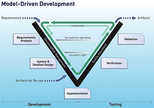
Figure 1: A “V” process roadmaps continual validation and verification of the developing system
The V process shown emphasises testing and verification at every stage of both analysis and design. This approach pushes the actual software generation further downstream, as shown on the left side of the “V”, in favour of developing more models instead. Testing is concurrently and continually performed on the corresponding models, as opposed to once at the end of the developed iteration by testing the resulting source code.
In embedded systems development, it makes sense to broadly break the project into systems and software counterparts, which have corresponding modeling and testing activities that are defined in the next few sections.
Modeling at System level
Most embedded projects have a distinct systems engineering role; this is especially true for projects in the defence and aerospace sectors, and to a lesser extent for data communication projects. Regardless of the presence of dedicated systems engineers, most projects require significant amounts of system modeling and analysis before proceeding with software development. The main goal at this stage is accurate interpretation of project requirements and their unambiguous production into a system model, the latter being preceded by systems analysis. This involves not only creating models, but also pushing the completed work to software engineers for application development. A common issue while executing the latter step is that a minor mistake in the systems engineering model will be greatly exaggerated when implemented in the software design. Detecting the resulting software errors while testing source code proves to be costly, as all the preceding software layers need to be fixed before the error is finally traced to the systems modelModel Verification
Verifying the PIM’s accuracy largely eliminates the problem of a system-level error trickling down into an executable application. This can be accomplished if the modeling tool allows execution of the system model to study its behaviour and easily identify any potential problems that may inadvertently get passed downstream to software designers.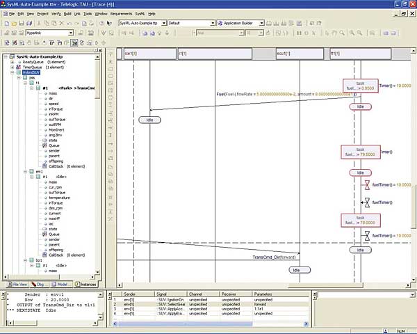
Figure 2a: A Sequence Diagram created by a Model Verification
Figure 2a displays the full execution cycle of a Sequence Diagram, as part of a systems engineering model. The underlying sub-system, a vehicle’s ignition management system, is exhibiting the behaviour associated with turning the ignition switch on. The animated interactions not only summarise the black-box behaviour of the components, but also furnish the instance values of the associated parameters such as, fuel flow rate, the RPM of the freshly started engine, and the ensuing demand for fuel. This execution data provides a sound basis for system analysis and ensures that both normal and boundary-level operating conditions of this sub-system are met. The white-box or detail design of the ignition sub-system is usually deferred to software designers who will add behavioural details, as shown in Figure 2b, and eventually generate source code from this model.
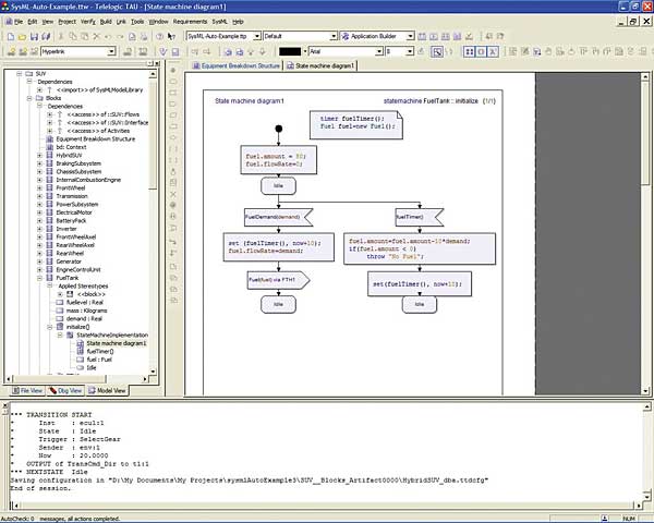
Figure 2b: Diagram illustrating the black-box behaviour of the sub-system
Software Modeling
A software designer (or engineer) is an expert in application development issues. This differs from a systems engineer, who is the domain expert with keen knowledge of the hardware and software technologies needed to realise the embedded product. While specifying the system components and black-box behaviour as shown in Figure 2a, system engineers also lay the groundwork for software development. For example, the detailed behaviour of one of the components, the vehicle Fuel Tank – shown in the Sequence Diagram as “ft(1)” – can be elaborated to a full-scale detailed behaviour as shown in Figure 2b, when software design is initiated. Subsequently, the software engineers added a path in the design of the system to pump fuel from the tank; based on the demand for fuel generated by vehicle’s engine management object. The systems engineers recognising another requirement later on augmented the design and added another behavioural path to the diagram, where they enabled a periodic check (through setting timers) of the remaining fuel in the tank and an error flag if the fuel tank is nearing empty.Note that in order to collaborate, the system and software specialists both need to use a convention that is easily understood by both parties; in this case a generic syntax also enables them to quickly revue and extend the other’s design. While software designers typically implement this level of detailed behaviour in source code, this is not conducive to cooperating with systems engineers on a design, because the latter group is either not familiar with the underlying programming language, or it may be intimidated by its detail. By designing the system in a high-level, Platform Independent syntax, both sides of the development team can together delve into the deepest levels of design detail. They can seamlessly cooperate on development of the final application without requiring platform-specific details like the Real-Time Operating System or the programming language that may not be easily understood by certain members of the development team.
Code Generation
The system detail in Figure 2b is sufficient to generate a full set of working source code for the Fuel Tank component of the vehicle design. However, the platform specificity needs to be added to the modeling tool either as an adaptation layer or directly into the modeled system’s diagram. In this way, the software engineer can form the Platform Specific Model (PSM) needed to develop code for the specific target platform. The modeling environment provides an environment for the software engineering team to generate and tailor source code which optimally executes on the platform, while being secure in the knowledge that the application itself remains correct and robust. Their focus is on efficient code. Changes in platform specifics and architecture are dealt with by generating a new PSM, without the introduced inefficiencies and bugs brought about by modifying at the code level.Conclusion
Platform Independent Modeling allows the application’s architecture to be developed and validated independently of the development of application code that will fit the target platform(s). This approach allows systems engineers to verify their high-level designs through execution of system models – without needing to add details on RTOS, language or other platform-specific information into the model. The software team can then focus on developing optimised source code for the selected target architectures, with the knowledge that the application is working and tested. In this way, organisations get the best of both worlds – a device that fully addresses and meets the requirements of a working application, coupled with an efficient implementation.Irv Badr has nearly 20 years of experience as a technologist, working out of Telelogic’s Chicago office. Irv Teaches Marketing and Technology Management courses at the Graduate School of Business at Loyola University in Chicago.
References
|
Comments