What is an Artifact?

What set of artifact templates should you have in you toolkit? There is no one size fits all answer to this question because every company is different and processes vary between companies and even within companies. You will need to research what will work for you, but to get you started I will provide a set of architectural phases and the artifacts that I find useful in each phase. Also to continue your research, Mike Vincent wrote an article for IASA (International Association of Software Architects) titled Software Architecture Tools that can be found in the IASA Skills Library.
This article has an excellent bibliography for further research into artifacts. There are many types of architectural artifacts that can help the communication of various IT architectures.
You should create a toolkit of artifacts types or templates so that there is consistency across team members and projects for the same reason that naming standards for servers and code standards for developers are established, making it easier to get started, for other architects to be integrated into the process, and to maintain and read by other team members. Here is a list of artifacts that are in my toolkit and can be used as a starting point for yours. Remember there is no one way to do this and the artifacts that you choose will depend on the architectural processes that you use.
Modeling
There are two general extremes when it comes to modeling languages. You can use the informal Box and Line methodology to a formal modeling language standard like UML (Universal Modeling Language). Box and Line diagrams are great for high level designs and also work well if you are using Visio for your modeling needs. They are easy to understand by non-technical people and easy to create. I use this modeling approach when defining conceptual architectures or working with agile project teams on the overall design. They particularly work well when all of the team members work closely together.On the other hand, UML is about standardizing the modeling language to make it more supportable by tools and create a common taxonomy for modelers. It defines a number of types of diagrams and elements that try to make the model as unambiguous as possible. A more rigorous adherence to UML may be required if you use a suite of software tools that use UML for your SDLC. You may also be more rigorous if you are outsourcing many parts of the project and require much more unambiguous artifacts. It is also useful on parts of the system where the design is complex and the developers will need to have clear direction.
Generally, people don’t use the full specification of UML. They use it as a basis for different diagrams but don’t use all of the details or symbols correctly. Remember, the ultimate goal is to communicate specific things about the design of the project to current team members and document the system for future support.
Requirements Phase
RACI Diagrams
RACI is an acronym that stands for Responsible, Accountable, Consulted, Informed. The purpose of this diagram is to describe the roles and responsibilities for a team or process. You generally matrix tasks with roles in this type of diagram and identify what each roles involvement is.
Example:
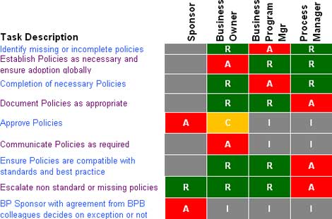
Source: Wikipedia
I like to have these created for a team so people know how everyone is involved, but more importantly, I like these defined for processes. For example, I create one for deployment to make sure everybody understands who is doing what. I also have this defined for architecture review processes.
Business Requirements and Backlog Documents
The business objectives and look and feel for the system are contained in the Business Requirements Document (BRD). Depending on the process you are using, this may look slightly different and be called different things (traditionally it is called the BRD, but in Agile processes it can be referred to as Storyboards or the backlog. It basically is a word document that states what the system should do from a business perspective. You will use or maybe even need to generate this as an architect to create the architectural requirements which is a mixture of functional and non-functional requirements to meet the goals of the project.
Examples:
For business requirements, see the Typical Deliverables section for a Business Analyst on Wikipedia.
You can get sample backlogs and various other agile process artifacts at Agile Software Development.
Use Cases
A use case describes the interactions between the users (called actors) of the system and the functions that they perform in the system. They aid in breaking up a complex system into the roles the users play and the functions they perform.
More information with examples, external links and reference material can be found on Wikipedia under Use Cases.
Architecture Requirements Document
This is a document that specifies what is required from the architecture. It is a combination of the business requirements that are pertinent to the architecture and the non-functional requirements. This is generally in the same format as a BRD or backlog depending on the SDLC in use.
System-Wide Qualities/Non-Functional Requirements
These represent the requirements that are needed for a functioning system, but are not the reasons why the system is being built. They support the system being built so that it works. Example non-functional requirements are:
Audit and control, Availability, documentation, efficiency, extensibility, scalability, usability, quality, price, reliability maintainability, security, performance, response times, etc.
You should get as specific requirements for each of these as you can. The system should be fast is not a good requirement. The system should respond in 2 seconds or less 80% of the time is more specific and verifiable.
This is generally in the same format as a BRD or backlog depending on the SDLC in use.
Architecture Design Phase
Design Specification
This is a document that describes the approach and reasons for the design. It generally will be used to organize the artifacts in the design phase. I generally have an Introduction that describes the approach and design and then have a section that covers each of the following:
Architecture Principles/Guides
I create a document that serves a standard template for this and represents the company’s culture and priorities when it comes to building systems. Each project will then modify this document if necessary. These are simple statements that are easy to remember and will guide the architecture.
Example Principles:
Security: Applications should ensure data and access security
- Sensitive data must be protected in storage and in transit
- People should have single identity to all enterprise applications (single sign-on)
- Usernames should be consistent across applications
Ownership: Clear and explicit ownership of enterprise data
- All enterprise level data entities should have a single identified system of record
- Systems should fulfill their custodial obligations for data they are the system of record for
Leverage assets: Leverage existing services and capabilities
- Leverage capabilities in our existing investments where appropriate (PeopleSoft, Data warehouse, roles, infrastructure, etc.)
Real-time: Minimize latency of data updates
- Minimize latency of data updates
Available: Minimize downtime and performance issues
- Critical Systems should be designed to avoid restarts or other downtime
- Systems should meet response time requirements
Patterns/Styles
Patterns and styles are well established solutions to problems. There are many types of architectural patterns and styles that help solve many common problems. An architect should avoid reinventing the wheel and research various patterns\styles that may meet their design needs. Each of these defines the pattern or style, give design guidance, show examples of how it is used. This is a topic for its own article but you can get further information at:- Architectural Pattern article on Wikipedia
- Roger Hill’s article on Architectural Styles at IASA
- Book: Pattern-Oriented Software Architecture: A System of Patterns, Volume 1 by Frank Buschman et al., John Wiley & Sons, 1996
Conceptual Architecture
The conceptual architecture is a high level overview of the components and interactions of the system(s). This is sometimes referred to as the back of the envelope design. The intent is to start breaking apart the system and get an idea of what services and components the system will provide. You do not want to show every detail of the interfaces at this level. A box and line diagram works really well for the conceptual architecture as shown in the following example for apache modules.
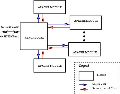
You generally run the conceptual architecture through a number of iterations to produce more detail in the components until you feel you have enough information to more to the Logical Architecture.
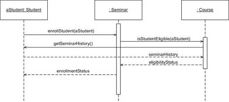
Logical Architecture
The logical architecture defines the details of the interfaces and interations of the services and components that make up the application. This architecture is used by the developers that build and assemble the parts of the application. I generally rely on the following UML artifacts to define complex interactions or components in this part of the design.
Sequence Diagrams – Used for defining the order of calls onto services, components and classes and the interfaces that are used. Sequence diagrams are very useful and I use them on most projects.
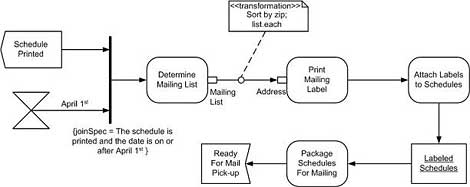
Process/Activity diagrams – Used to describe a business process, workflow or complex business rule.
Architecture Review Phase
Architectural Test Plans/Validation
A list of thought exercises and/or walk through scenarios that will look at the various design elements and step through the architecture to make sure that it meets the business and architecture requirements. Other experts use this to look for various problems or gaps that may exist in the architecture. I basically use the architecture requirements that is subset of the business requirements (the ones that matter to the architecture) and the non-functional requirements for each section heading and then list any tests or validation plans under each one if required.
Prototypes
For complex and new functionality or very risky areas of the architecture, I will have the developers build a prototype to validate whether something will work or not. This takes a minimal part of the architecture through to implementation to prove something will work as designed or not.
Deployment Phase
Deployment Diagrams
Distributed software architectures can be deployed a number of ways. If you are working for a specific company and delivering a custom solution, you will typically define one deployment specific for the company and meets the needs of the architecture requirements like performance and availability. If you are selling a software product, you will usually define a number a deployment scenarios and state what each is trying to maximize or minimize that your deployment engineers and customers can use in defining how they will deploy the software. There are two approaches to this depending on the type of modeling you are using. UML has a Deployment Diagram type that can be used to represent the deployment of a software project.
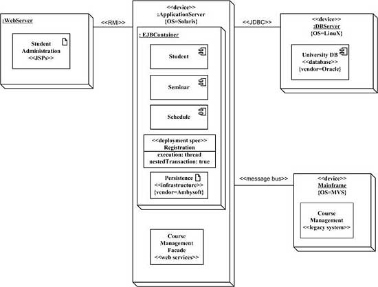
I tend to use the UML Deployment Diagram because it is very similar to a box and line diagram and easy to read. You could also overlay this information on the Infrastructure diagram.
Infrastructure Diagram
An Infrastructure diagrams is useful during this phase because it defines where the physical servers and IT infrastructure components are. It also provides information about their names and their configurations. This information is the basis for the deployment diagram.
There are a large number of choices when it comes to artifacts that you will use to document your architecture. I showed you the artifacts that I use and find useful in my processes currently. This will most likely change and evolve as the organization I work for changes and evolves. The point is that you need to figure out what artifacts work with your organization and processes. You then need to establish a standard set of artifacts that the architects can work from.
More Information:
Mitch Ruebush is the Leader of the Architecture Team for ING DIRECT, the largest direct bank in the U.S. He is president of the Philadelphia chapter of the International Association of Software Architects, and serves on the IASA Board of Directors. He has authored many books and articles and speaks at a number of events each year.
![]()
Comments